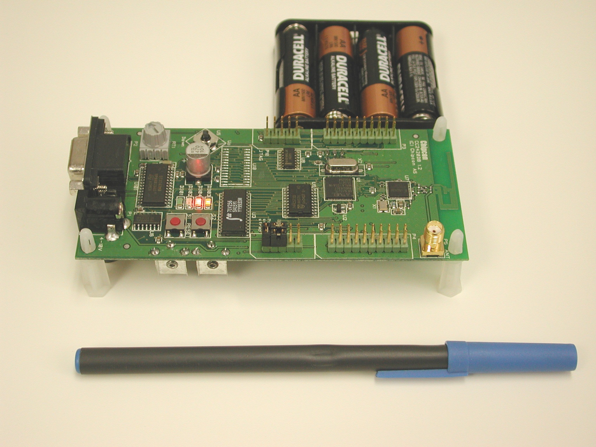
Chipcon's CC2420DB demonstration board comes with a CC2420 RF chip, Atmel Atmega128 microcontroller, 32 KB external RAM, a printed antenna, joystick, buttons, LEDs and other basic support components. Figure 1 (below) is a picture of one of the CC2420DB boards, in comparison with a 6 inch scale.
Figure 1: Chipcon CC2420DB Demonstration Board
Currently, we are primarily using the Chipcon boards for testing purposes (the other option being Radiocrafts boards, discussed later). In order to measure the amount of power consumed in different modes of operation, the boards were programmed to transmit packets(0 dBm Transmit Power), sleep and idle for certain time-periods. Each of these operating modes was triggered by a timer. For instance, in the case of an end-device, the board was set up to first process the bind event. After binding with the coordinator, it would go to lite sleep for 30 seconds. At the end of the 30s period, a TX-event would be fired which would wake up the end-device for transmission. Once transmission is completed, the device would be operating in RX (idle) mode for sometime, until the next event to put it to deep sleep gets fired. Power consumed in each of these modes was measured and recorded, as shown in Table 1 below.
| Operating mode | Current (in mA) | Voltage (in V) | Power (in mW) |
|---|---|---|---|
| Idle+ | 326 | 5.99 | 195.56 |
| TX+ | 616 | 5.99 | 369.54 |
| RX+ | 456 | 5.99 | 237.54 |
| Sleep Lite* | 2 | 5.99 | 11.99 |
| Sleep Deep* | 2 | 5.99 | 11.9 |
Table 1: Power measurements for CC2420DB boards in different operating modes
Bandwidth tests were performed by configuring one of the boards as a transmit-router and the other as a receive-router. The transmitter was set up to generate 120 packets of 85 bytes each and send them out to the receiver. Each 85-byte packet consisted of some data, along with a CRC checksum and a packet sequence number. The Network Layer ACKs were turned off for this test case. At the end of the 120-packet transmission, the transmit- router sent out an end-of-frame packet to the receive-router. The receiver at the other end would start a timer on receiving the first packet and stop it at the end of the entire transmission, hence measuring the time taken (t) for transmission. It would then use t to compute the bandwidth for this 10,200 byte transmission (120 pkts x 85 bytes/pkt, approx. 10KB) and send this bandwidth across to the transmitter. We used the packet sniffer to read this value and record it. Alternatively, we could also read out the bandwidth value via the hyperterminal using a serial port application that we wrote. These tests are being conducted with the 2 antennas facing eachother, as shown below. Also, in all cases except the last (125 feet), we had the CC2420DB boards placed on the carpeted wooden floor of our lab. It was only for the final 125 feet case that we had to place the boards on a pedestal to get the boards talking with eachother.
Antennas facing eachother
Table 2a below consists of the readings that we obtained in our bandwidth test experiment. The test was done indoors, using 3 CC2420DB boards (transmitter + receiver + coordinator) with the printed antennas placed parallel to eachother, TX and RX antennas facing eachother (setup shown below).
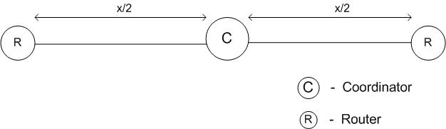
Total Bytes Transmitted: 10KB, no NWK ACKs Antenna Orientation: Facing Eachother Environment: Inside the Lab
|
S. No. |
Distance (in feet) |
Bandwidth (in bps) |
|
1 |
25 |
170,711 |
|
174,358 |
||
|
172,881 |
||
|
2 |
50 |
170,711 |
|
67,017 |
||
|
173,648 |
||
|
67,538 |
||
|
171,789 |
||
|
66,174 |
||
|
3 |
75 |
70,761 |
|
72,711 |
||
|
69,628 |
||
|
4 |
100 |
171,789 |
|
63,648 |
||
|
170,711 |
||
|
172,881 |
||
|
5 |
125 |
68,233 |
|
71,793 |
||
|
66,355 |
Table 2a: Bandwidth test indoors with CC2420DB, for 10KB payload
As can be seen from the table above, our bandwidth test was done for various distances between the transmitter and the receiver. In the first case, we had the TX and RX devices 25 feet apart, with the coordinator placed in between both of them. In this 25 feet case, the transmitter communicated directly to the receiver in a single hop and bandwidths were consistently obtained in the 170Kbps range. The 50 feet case though seemed to be quite varying in behavior. The data transmission took place in a single hop (direct TX to RX) on some occasions, while at other times it would use the coordinator to route the packets, hence taking 2 hops to transmit the same data. In the single hop case, the bandwidth was found to be in the 170+Kbps range. Whereas, in the 2 hop case, since each packet needed to be transmitted via the coordinator, the bandwidth was under 70Kbps, lesser than half the single hop value. Another noteworthy point with respect to the 2 hop case is that some of the packets sent out by the transmitter seemed to get queued at the coordinator. So the coordinator received packets at a faster rate than it transmitted them, which could have an added effect on the already reduced bandwidth. For the 75-feet separation case, we observed that the bandwidth was consistently in the 70Kbps range, again the reason being that every packet needed 2 hops to be transmitted from the source to the destination.
Until this period, it seemed as if a separation of 50 feet between the transmitter and the receiver was the borderline case where data transmission might sometimes occur in a single hop and at other times might need to be routed via the coordinator that was placed exactly in the middle of both the transmitter and the receiver. But this theory was proved wrong when we moved on to test the 4th case, wherein the transmitter-receiver separation was increased to 100 feet. In this case we noticed that both end devices were still capable of communicating with eachother directly, without any need for the middle coordinator in most cases. This was when we saw better bandwidths of 170+Kbps. But then, there were also some instances (though fewer than in the 75 feet case) when the coordinator in the middle was used for routing traffic, hence bringing down the bandwidth back to the 60-70Kbps range. In the 125 feet case, we certainly saw a deterioration in transmission behavior. Infact, we noticed that the 2 end-devices had to be raised from ground-level in order to even bind with the coordinator and transmit data packets between eachother. So, on raising the 2 end-devices and the coordinator by about 2 feet above the ground, we noticed that the devices were able to communicate with eachother via the coordinator, with bandwidth ofcourse dropping down to the lower range of around 70Kbps. We also saw most errors and packet drops in this last case.
From the above observations, it is clear that for distances of 25 feet or lesser, the devices are capable of talking directly with eachother. On the other extreme, for a separation of around 125 feet, the devices are less reliable and also surely seem to need the coordinator in the middle. But the 50-75 feet cases still need more experimentation in order for us to come to a logical deduction.
The above tests were repeated for a larger payload size of 100KB. The experimental setup was the same as used in the previous case, transmission was done with NWK ACKs turned off. We noticed in Table 2a that the devices seemed to talk with eachother better when raised above the ground by a few inches (125 feet case). We therefore conducted the following tests with all 3 devices placed on a pedestal at a height of about 2-3 inches. Our observations for this 100KB payload size are as shown in Table 2b.
Total Bytes Transmitted: 100KB, no NWK ACKs Antenna Orientation: Facing Eachother Environment: Inside the Lab
|
S. No. |
Distance (in feet) |
Bandwidth (in bps) |
|
1 |
25 |
167,932 |
|
173,801 |
||
|
172,552 |
||
|
2 |
50 |
62,294 |
|
64,067 |
||
|
62,369 |
||
|
3 |
75 |
156,793 |
|
149,974 |
||
|
158,950 |
||
|
4 |
100 |
157,768 |
|
159,312 |
||
|
158,354 |
||
|
5 |
125 |
151,432 |
|
157,677 |
||
|
153,659 |
Table 2b: Bandwidth test indoors with CC2420DB, for 100KB payload
The above test case was carried out as in the previous test setup. The important change in this case is transmission of 100KB of total data. From our previous test case experiment, we found boards at 2-3 inches above ground performed better for distance of 125 feet apart. To achieve better results, this scenario was executed by having 2-3 inches pedestal under the boards. The boards at a distance of 25 feet seem to work well with an average bandwidth ~170Kbps. This is marginally lesser than previous case for 10KB data. Hence the reduction in bandwidth is acceptable. For a distance of 50 feet a similar reduction pattern was observed. But the bandwidths remained consistent over the 3 iterations. Keeping the boards further apart at distances of 75 feet, 100 feet and 125 feet had uniform decline in the bandwidth. The channel association time and binding process did take a little more time in the 125 feet case. The extra time taken could be around 10 seconds. An important part of the analysis is the actual number of packets sent out. No packets were dropped, instead there were a lot of retransmissions. There were no patterns as to when the retransmissions took place. The possible reasons are yet to be determined and analysed further.
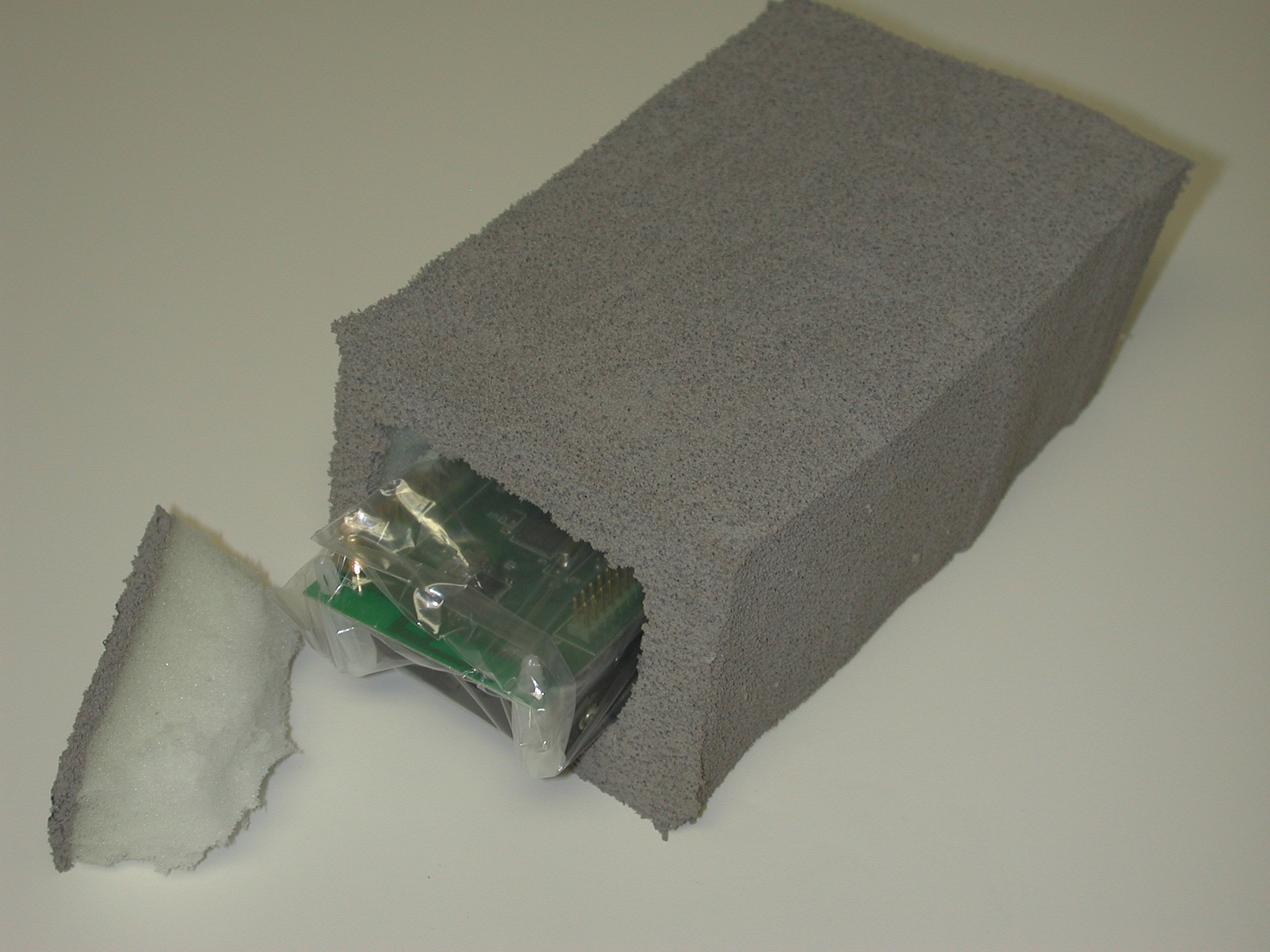
After conducting 2 experiments indoors (one each for payload sizes of 10KB and 100KB) we decided it was time to take them outdoors. The setup was once again similar to the previous cases -- coordinator in the middle of sender and receiver, all 3 devices placed about 2-3 inches high, NWK ACKs turned off. One other difference in these tests were that we wrapped the devices with plastic covers (for weather-proofing) and placed them within fake rocks in order to simulate realistic deployment scenario (shown in figure below). Table 2c below has our observations for the 10KB payload size.
 |
 |
|---|---|
 |
 |
Total Bytes Transmitted: 10KB, no NWK ACKs Antenna Orientation: Facing Eachother Environment: Outside the Lab
|
S. No. |
Distance (in feet) |
Bandwidth (in bps) |
Dropped packets (in %) |
|
1 |
25 |
159,362 |
- |
|
166,871 |
- |
||
|
165,517 |
- |
||
|
2 |
50 |
61,770 |
3 |
|
158,046 |
< 1 |
||
|
157,528 |
- |
||
|
3 |
75 |
161,904 |
- |
|
155,316 |
- |
||
|
157,528 |
- |
||
|
4 |
100 |
160,946 |
- |
|
171,069 |
- |
||
|
63,046 |
< 6 |
||
|
5 |
125 |
69,716 |
8 |
|
172,881 |
< 7 |
||
|
166,530 |
- |
Table 2c: Bandwidth test outdoors with CC2420DB, for 10KB payload
The above experiments were carried outside the lab with boards embedded inside the fake rocks. The results tabulated in the above table show the bandwidth is better than inside the lab. Inside the lab, the declined bandwidth could be due to interference with wireless devices and metal surfaces. When carried outside, all the three boards were maintained above the ground at 2-3 inches.
Total Bytes Transmitted: 100KB, no NWK ACKs Antenna Orientation: Facing Eachother Environment: Outside the Lab
|
S. No. |
Distance (in feet) |
Bandwidth (in bps)* |
|
1 |
25 |
170,390 |
|
171,356 |
||
|
161,552 |
||
|
2 |
50 |
160,125 |
|
158,099 |
||
|
151,813 |
||
|
3 |
75 |
172,515 |
|
170,747 |
||
|
170,961 |
||
|
4 |
100 |
171,753 |
|
158,971 |
||
|
160,440 |
||
|
5 |
125 |
160,819 |
|
160,819 |
||
|
161,648 |
Table 2d: Bandwidth test outdoors with CC2420DB, for 100KB payload
Total Bytes Transmitted: 400KB, no NWK ACKs Antenna Orientation: Facing Eachother Environment: Outside the Lab
|
S. No. |
Distance (in feet) |
Bandwidth (in bps) |
|
1 |
25 |
167,252 |
|
172,771 |
||
|
172,103 |
||
|
2 |
50 |
160,978 |
|
66,206 |
||
|
171,843 |
||
|
3 |
75 |
168,082 |
|
167,460 |
||
|
169,285 |
||
|
4 |
100 |
63,328 |
|
165,567 |
||
|
169,092 |
||
|
5 |
125 |
155,827 |
|
168,218 |
||
|
168,604 |
Table 2e: Bandwidth test outdoors with CC2420DB, for 400KB payload
From the above tables with bandwidth measurements, we see that no matter what the payload size is, no matter whether the experiment is performed indoors or outdoors, if the transmission from sender to receiver occurs in a single hop, the bandwidth seems to be in the range of 150-180Kbps. Similarly, if the transmission takes 2 hops, then the bandwidth range comes down to 60-80Kbps. Though we could say for certain that for outside experiments we saw single hop transmissions for longer distances as compared to the inside experiments.
Another common observation was with the bandwidth for 50 feet end-to-end distances. There is an observed drop in bandwidth for 50 feet. This seemed to occur quite consistently in all scenarios with data transmission taking 2 hops more often than in other distances. A possible reason for this could be the RF patterns at a distance of 50 feet, although this is not conclusive.
The following observations, in Table 3 below, represent a test case wherein 10KB size payload was transmitted in the outdoor environment with network layer ACKs turned on. With the extra ACK packets being transmitted in this case, we expected to see a fall in the bandwidth values, as can be seen from the measurements obtained. The setup consisted of 3 devices (Transmitter-Coordinator-Receiver) for the most part, until we reached 100 feet. From 100 feet onwards, we added an extra router between the Transmitter and the Coordinator (hence making the new setup Transmitter-Router-Coordinator-Receiver).
Total Bytes Transmitted: 10KB, with NWK ACKs Antenna Orientation: Facing Eachother Environment: Outside the Lab
|
S. No. |
Distance (in feet) |
Bandwidth (in bps) |
Dropped packets (in %) |
|
1 |
25 |
72,379 |
- |
|
78,764 |
- |
||
|
71,641 |
- |
||
|
2 |
50 |
76,404 |
- |
|
80,357 |
- |
||
|
63,456 |
- |
||
|
3 |
75 |
60,678 |
- |
|
41,402 |
- |
||
|
39,060 |
- |
||
|
4 |
100 |
69,834 |
< 5 |
|
70,588 |
- |
||
|
75,836* |
- |
||
|
20,791* |
> 50 |
||
|
5 |
125 |
29,288* |
> 50 |
|
35,819* |
> 50 |
Table 3: Bandwidth test outdoors with CC2420DB, for 10KB payload with NWK ACKs
In this scenario, with NWK ACKs turned on, we initially observed a huge percentage of dropped packets. This was due to the following reason: Each time the transmitter sent out a packet, the receiver sent back an ACK in response. The problem we noticed here was that the transmitter would send out a few packets at a stretch. And then, when it received ACKs for these packets, it would still try to continue transmitting more packets. So there would be a clash at the transmitting-end, between the new packets the transmitter attempts to send and the ACKs it received for the previous packets that got delivered to the receiver. In the process, many of the packets would be dropped at the transmitting-end itself. In order to get around this issue, we had to make a few adjustments at the application level so that the transmitter would have a small time-lag between consecutive transmissions. This way, the ACK for an earlier transmission would be received by the transmitter before it attempted the next transmission. This solution seemed to work for the most part.
The bandwidths obtained for this case were much lower than the "no ACKs" scenario. We noticed that even when transmission took place in a single hop, directly from the transmitter to the receiver, the bandwidth was only in the range of 60-80Kbps. Somewhere around the 75 feet distance, the transmission seemed to take place via the coordinator in the middle, hence making 2 hops. This was when the bandwidth reduced to around 40Kbps. Around the 100 feet mark, the transmitter was using multiple hops for communication quite consistently. We therefore started to use a 4-node setup from the last 2 readings for 100 feet distance onwards. In the third reading for 100 feet, we got a bandwidth in excess of 75Kbps since the 2 ends (transmitter and receiver) talked directly with eachother in a single hop, although they used the middle router and coordinator to initially establish the network. In the fourth reading, the 2 ends seemed to use the middle router and coordinator throughout, the transmission took place over 3 hops, hence bringing down the bandwidth to only about 20Kbps. We also started observing huge packet drops from this point on. For a distance of 125 feet, it was very difficult to get measurements as there were large amounts of dropped packets and the packet transmission hardly ever got completed all the way to the last packet. But we did manage to take 2 readings, though error rates were very high. The transmission seemed to occur in 3 hops the first time and in 2 hops the second time.
In order to determine the different signal strength levels that these boards can achieve at varying distances, we plan to perform tests using the 4 on-board LEDs as signal strength indicators. With the 4 LEDs, we will be able to find out the maximum distances up to which the boards can maintain signal strengths of 100%, 66%, 33%.... These tests will be performed with the on-board printed antennas as well as with the external antennas.
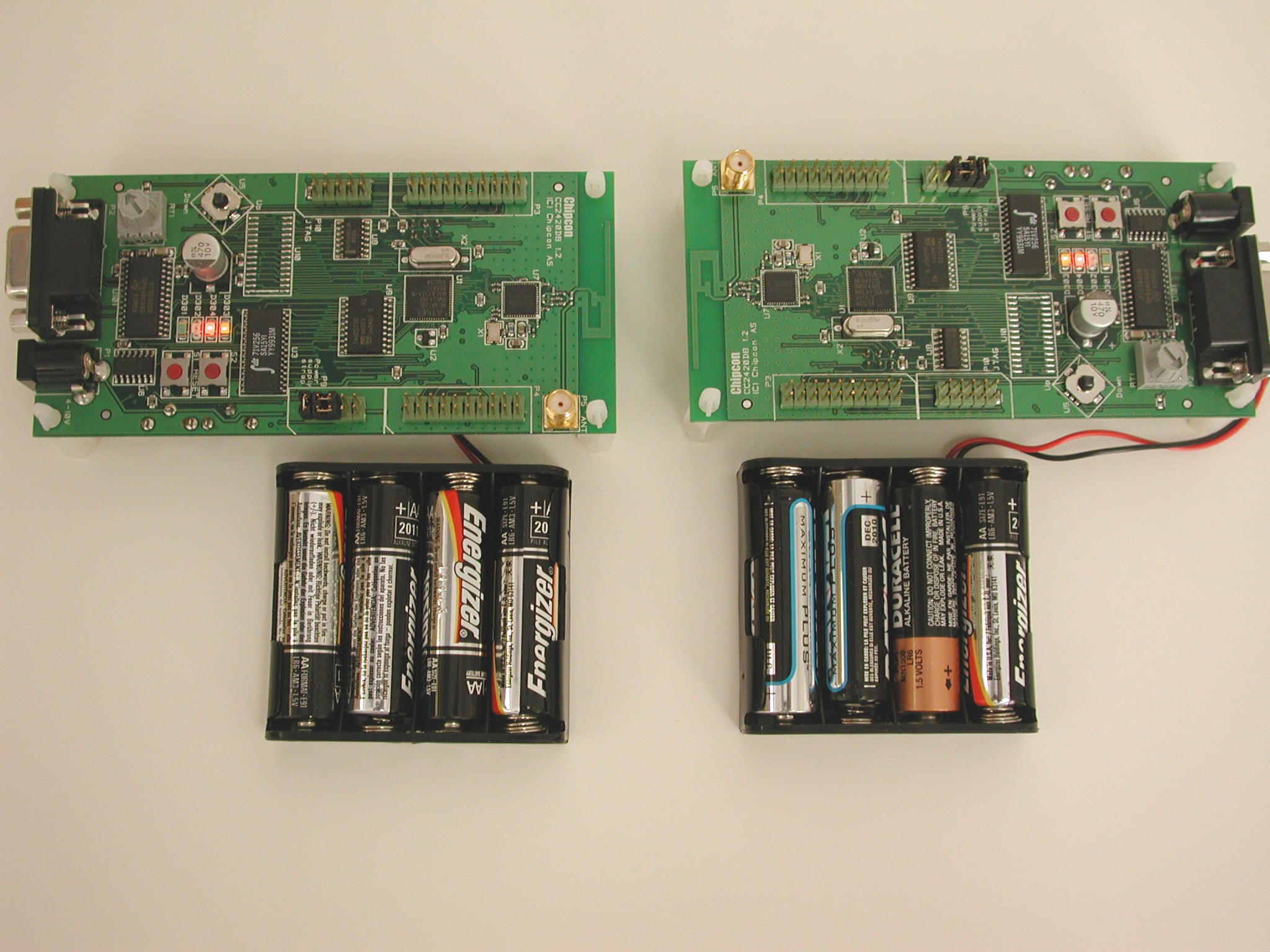
Radiocrafts RC2200DK boards are modules similar to Chipcon CC2420DB except that Radiocrafts boards don't have External RAM and instead of joystick they have 6 switches. Below is a picture (Figure 2) of the Radiocrafts RC2200DK with external power supply.
Figure 2: Radiocrafts RC2200DK Demonstration Board
For Radiocrafts boards, the same application software was used as in Chipcon CC2420DB boards. There were some low level changes to make the compatibility of the LEDs. We would like to highlight upon this experiment's facts that we were not able to bind the End Device on a Radiocrafts Board (We have talked about the issues later in next section). Hence for TX power measurement, packets were sent to Coordinator. The detailed power measurements are given in Table 3 below.
| Operating mode | Current (in mA) | Voltage (in V) | Power (in mW) |
|---|---|---|---|
| Idle* | 16.6 | 5.99 | 99.58 |
| TX* | 48.5 | 5.99 | 256.15 |
| RX* | 35.5 | 5.99 | 212.96 |
| Sleep Lite* | 7.9 | 5.99 | 47.39 |
| Sleep Deep* | 7.9 | 5.99 | 47.39 |
Table 3: Power measurements for RC2200 boards in different operating modes
Due to the long delays in receiving the Radiocrafts hardware, the time spent in trying to optimize this configuration to improve power consumption was minimal. Additionally, with the difference in hardware configuration already observed, it is possible that some of the components on the board remain "on" even when in sleep modes, which could be a possible explanation for the higher power consumption observed in the sleep modes (as compared with Chipcon's sleep modes).
This test case should be carried out using the same software application that was used for Chipcon CC2420DB boards with minor changes. We had the following issues with compiling/loading same Chipcon board Z-stack on Radiocrafts board: