|
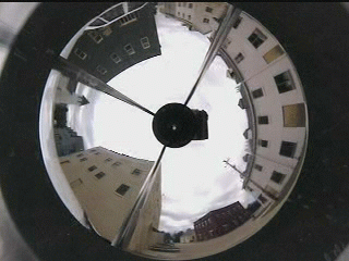
an Application of Omni-Directional Imaging Remote Reality is an approach to providing an immersive environment via the use of omni-directional imaging. The remote reality environment allows the user to naturally look around, within the hemispherical field of view of the omni-directional camera, and see objects/actions in that view. It can use live or pre-recorded video from a remote location. While less interactive than traditional VR, remote reality has important advantages: there is no need for "model building," and the objects, textures, and motions are not graphical approximations. This document will provide an overview of past, present, and future work in remote reality at Lehigh University, see also C. Power's Remote Reality Page . We begins with an overview of omni-directional imaging. The second section describes the current remote reality system and smaller, more portable designs we are looking at. The next section focuses on applications of remote reality currently under development. Finally, the document ends with a few example video's, and some brief comments about and a link to our Teleoperation Experiment. In addition, you can take a look at some remote reality pics in the photo gallery. Omni-Directional Imaging Overview Omni-directional imaging refers to the ultimate wide-angle lens, a system that can capture an image in every direction. Over the years many such systems using moving cameras or "fish-eye" lenses have been developed to generate "approximate" omni-directional images. They are only approximate because they do not have a single perspective "viewpoint", but a collection (finite or in the case of most fish-eye lenses, an infinite locus of points). The newest systems, which use special devices to attempt to rotate about the "perspective point" of a lens attempt to reduce the distortions caused by the varying viewpoints, have been greatly improved for construction of omni-directional "static" images. Setup and "calibration" of these cameras, as well as controlling movement in the area being imaged, requires care and planning. The development of the Remote Reality system was made possible by the recent research of S. Nayar, which revolutionized wide-field of view imaging by introducing the paracamera (used interchangeably with omni-camera in this document), a system that directly captures a full hemisphere (or more) while maintaining a single perspective viewpoint. (see Columbia's CAVE web site for more info on Omni -Directional imaging, Cyclovision's web site for details on commercial omni-directional cameras, and our omni-directional VSAM effort. (joint with S. Nayar Columbia Univ) Because the Paracamera captures the viewing hemisphere (or more) simultaneously, it can be used for full motion video. Furthermore, placing two paracamera systems back-to-back allows a true viewing sphere, i.e. 360 x 360 viewing. Unlike fish-eye lenses, each image in the paracamera system can be processed to generate GEOMETRICALLY CORRECT perspective images in any direction within the viewing hemisphere. The omni-directional imager combines an orthographic lens and a parabolic
mirror, where the axis of the parabolic mirror is parallel to the optic
axis. To see how we generate a proper perspective image from the para-image, consider an "imaging array" in the desired viewing direction. For each pixel, logically cast rays toward the focus and follow them as they "reflect off" the parabolic surfaces focus and follow them to where intersect the measured image. The resulting spatially varying resampling can be very efficiently implemented using spatial lookup tables. In the remote reality system, when turning the HMD (or giving commands to zoom-in or zoom-out), the virtual viewpoint is stationary; only the location of the virtual "imaging array" is moved. Thus the transitions between views is very very natural. While we are describing the remote reality system using a HMD and head tracker to control viewing, we also note that the system could (and the commercially available software from Cyclovision does) use a mouse or joystick to control viewing and the window in a regular computer display to show the resulting unwarped image. The Remote Reality System The main components of the remote reality system are the omni-directional camera, video recording systems, PC computing platform, head-mounted-display (HMD), and head-tracker. The current system balances cost and quality. Our current data collection system was approximately $5K and the computing/HMD/head-tracker play-back system was about $3K. Prototypes using a wearable computer are currently under development(see below for more details on those). Because omni-directional imaging compresses a viewing hemisphere into a small image, maintaining resolution and captured image quality is quite important. While the process scales to any size imager, the current system uses NTSC (640x480) or PAL (756x568) cameras. Note the "spatial resolution" of the image is not uniform. While it may seem counter intuitive, the spatial
resolution of the omni-directional image is GREATEST along the horizon, just objects are most distant. The spatial resolution along the horizon is 4.2 The playback system uses a 200-300MHz MMX CPU (running Linux), and a video capture card. The system computes monocular SIF-resolution full-rate "video" (320x240@30 fps NTSC) which is reasonably well matched to the Virtual I-O glasses. The built in head tracker of the I-O glasses, provides yaw, pitch, and roll, with updates to the viewing direction at 15-30fps. A mouse or joystick can also be used for view selection. A lower speed CPU could be used for playback at 30fps, but cannot update the viewing direction at that rate. Wearable/Portable
Systems
Understanding the user interface issues of immersive video and wearable computing in a subject of our ongoing work. Mpeg video's of some of the different interfaces we are exploring are:
In addition to the wearable system, two very portable systems are also in development. By very
The second portable remote reality system we have in development is designed primarily for use by
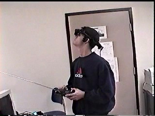
Applications of Remote Reality More recently our efforts have been focused on developing applications of the remote reality system. Its applications in entertainment are rather obvious. More direct applications include training and mission rehearsal (for military actions), real-estate sales, education, and remotely piloted vehicle operation. The later, remotely piloted vehicle operation, also known as teleoperation, is one of our main areas of interest. The prototype system (seen at right) was developed in hopes of proving the feasibility of the technology using a cheap off the shelf R/C car and other commercially available products. Several areas are of main
The vehicle itself is a cheap ($150) R/C car purchased for its large size (16"L x 12"W x 10"H) and ground clearance (approximately 6"). The large size enables it to be a stable camera platform, and the high ground clearance is useful for clearing small (2-3") objects. To control the car, the radio transmitter/receiver pair that came with the car were used. They operate at 27MHz and have a range of about 50-75 ft. Two different camera systems were tried on the prototype to evaluate their quality, geometry, and weight. The camera system seen at right is an early omni-cam prototype that uses a Panasonic Digital Color CCD camera. These cameras are quite heavy and the car's performance was severely degraded as a result. The camera system used predominantly for early testing was a commercial version of the omni-camera available from Cyclovision. It is slightly lighter, has better weight distribution, and worked fairly well even in low light situations. For video transmission, we used a transmitter and receiver we happened to have in the lab already. The system is a 2.4GHz based Tx/Rx pair that can operate on four different user-selectable channels. It requires 12 volts DC and for the purposes of testing the vehicle we chose to use (2) 7.2 volt R/C batteries wired together is series. These batteries added significantly to the weight, but were able to be quickly recharged. The results of the initial tests on the vehicle were promising. We found that it was possible to effectively pilot the vehicle remotely. Early tests showed the advantages the omni-cam provided over traditional forward looking cameras. Our results were however not all positive. We found the effects of vibration and electro-magnetic interference from the car's DC motors and tx/rx equipment to be significant. We did however prove enough feasibility to warrant further testing, See the Teleoperation Experiment section for more information.
Due to the significant problems associated with the various aspects of the prototype's performance, it was necessary to redesign all of the major systems of the vehicle for further testing. The second generation prototype, known as the Para-RROVer or Parabolic Remote Reality Omni Vehicle, is a completely new design with the exception of the frame, tires, and motors. The frame and tires were kept because of the size and ground clearance they provided, and the motors were kept because they provided a good mix of speed versus runtime. Everything else on the vehicle has been upgraded for a variety of reasons that will be discussed next. The first thing to be replaced was the tx/rx system that came with the vehicle. The range it provided, 50 - 75ft., was completely inadequate for the purposes of teleoperation. It was replaced with a Futaba Skysport 4-channel FM system. This system not only increases the useable range of the Para-RROVer to over 4000 feet, it adds two control channels for possible future addition of a pan/tilt unit. Another major system that was replaced was the video transmitter and receiver. The original 2.4GHz system worked well, but was limited to line of sight transmission between the transmitter and receiver. This meant that the signal could not travel through walls, doors, or even humans, which makes for a poor transmission system for teleoperation. We found we
Another important component to be replaced was the camera. While the commercial version of the omni-cam being used was quite adequate, in that it was light, fairly sturdy, easily mountable, and had good low light characteristics, it had its drawbacks. The commercial version provided only modest quality video, was interlaced and therefore suffered from issues in that area, and had no means for on vehicle recording, something we determined was very important when performing experiments. The camera we chose to replace it was the Cannon Optura. It offers two main advantages over the previous cameras: (1) it is 640x480 progressive scan (non-interlaced) which gives better quality video with less interlacing effects, and (2) it can record the video on mini-dv's whereas the previous camera had no internal recording mechanisms. Another advantage is it uses a folded optics system (designed by T. Boult, L.U.), meaning the light reflects off the parabolic mirror, then off the planar mirror and into the camera's lens. The folded optics system allows the
One of the problems we encountered when adding the weight of the Optura was poor shock performance. The standard shocks the vehicle came with were never designed to withstand the heavy load being placed on them. They were replaced with heavy duty adjustable oil-filled aluminum shocks. These shocks have stiffer springs and provide better dampening than the original shocks. One final thing that must be mentioned is the effect of EM interference on the video signal. The EM interference emitted by the vehicle's electronics, as well as the Cannon Optura, is severe and must not be overlooked. Not accounting for this interference severely limits any video transmission system placed on the vehicle, no matter what it's capabilities. To combat this, we use proper placement of the transmission antenna, and EM interference blocking materials. We have tried mounting the transmitter several places on the vehicle, and the best to date has been the highest point. Placing the transmitter at the highest point achieves two things. First, it gets the transmitter as far away from any interference as possible, and second, no objects on the vehicle ever block the path from the transmitter to the receiver (unless of course the vehicle is above in elevation relative to the receiver). To block some of the interference, we rely on combinations of wire mesh caging, and aluminum foil. While that may sound crude, we have found they are good, inexpensive solutions to the problem of interference. The Para-Chopper The Underwater ParaCam
Various aspects of the Remote Reality system have been demonstrated at the 1998 JASON's meeting, the DARPA 40th anniversary celebration, CVPR98, Siggraph 98, the 1998 VSAM Workshop, WACV98, and the 1998 DARPA Image Understanding Conference. It has also been shown to various military groups and S. Peleg had a demo system running at Hebrew University for a while. Example Omni-Videos This section has a few videos from the paracameras, as they might be used in remote reality. These videos are MPEG clips of the raw unprocessed output, meaning they are fixed view. (The processed output will not be available until we get a new VGA->NTSC converter, a student plugged the wrong power-supply into our last one :-().
As was mentioned maintaining resolution is very important . We point out that to keep the size of the examples down, we have generated SIF resolution MPEG's. The reduction from 640x480 to 320x240 is a significant loss. In addition, Mpeg adds a bit of bluring and noise. We will (soon), have some of the processed 320x240 unwarped "output" associated with these clips, but with the loss of user control much of the impact is lost as well. Teleoperation Experiment Teleoperation, the remote operation of a vehicle or robot, has a growing list of applications. As the Para-RROVER demonstrates, the omni directional imaging sensor when combined with our remote reality system provides the tools necessary for teleoperation. For the we have a large experiment planned which will test the teleoperation capabilities of several interfaces to our remote reality system against that of a single wide angle lens. Click on the link above to read more about the experiment. |


 A biocular (true Remote-reality) HMD
 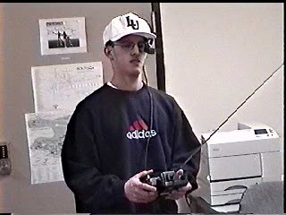 A monocular HMD
 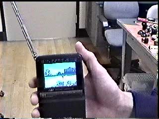 A "computer free" interface video broadcast to a
hand held TV
A "computer free" interface video broadcast to a
hand held TV


